Select the best Location
Indoor unit:
- Do not have any heat or steam near the unit.
- Select a place where there are no obstacles in front of the unit.
- Make sure that condensation drainage can be conveniently routed away.
- Do not install near a doorway.
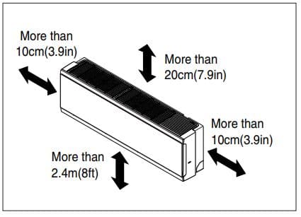
- Ensure that the interval between a wall and the left (or right) of the unit is more than 10cm(3.9in). The unit should be installed as high as possible on the wall, allowing a minimum of 20cm(7.9in) from ceiling.
- Use a metal detector or metal scanner to locate studs to prevent unnecessary damage to the wall.
Outdoor unit:
- If an awning is built over the unit to prevent direct sunlight or rain exposure, make sure that heat radiation from the condenser is not restricted.
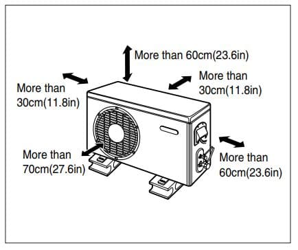
- Ensure that the space around the back and sides is more than 30cm(11.8in). The front of the unit should have more than 70cm(27.6in) of space.
- Do not place animals and plants in the path of the warm air.
- Take the weight of the air conditioner into account and select a place where noise and vibration are minimum.
- Select a place where the warm air and noise from the air conditioner do not disturb neighbors.
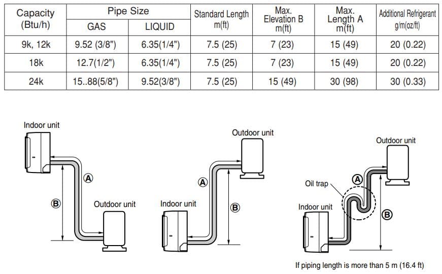
Piping Length and Elevation
Capacity is based on standard length and maximum allowance length is on the basis of reliability. Oil trap should be installed every 5~7 meters (16.4~23.0ft).
Fixing Installation Plate
The wall you select should be strong and solid enough to prevent vibration
- Mount the installation plate on the wall with type “A” screws. If mounting the unit on a concrete wall, use anchor bolts.
Mount the installation plate horizontally by aligning the centerline using a level.
- Measure the wall and mark the centerline. It is also important to use caution concerning the location of the installation plate-routing of the wiring to power outlets is through the walls typically. Drilling the hole through the wall for piping connections must be done safely.
- Install after removing one of the indicated cutting phase according to the installation location of the indoor unit’s piping.
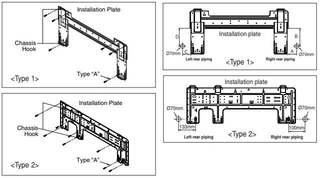
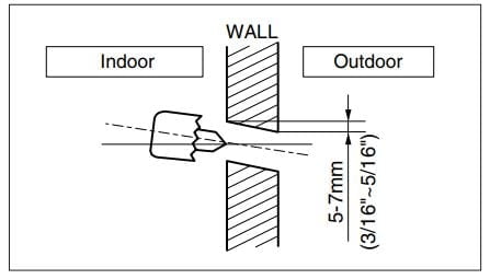
Drill a Hole in the Wall
Drill the piping hole with a ø70mm(2.76in) hole core drill. Drill the piping hole at either the right or the left with the hole slightly slanted to the outdoor side.
Flaring Work
Main cause for gas leakage is due to defect in flaring work. Carry out correct flaring work in the following procedure.
Cutting Tubes
- Use the piping kit accessory or the pipes purchased locally.
- Measure the distance between the indoor and the outdoor unit.
- Cut the pipes a little longer than measured distance.
- Cut the cable 1.5m(59.1in) longer than the pipe length.
Burrs removal
- Completely remove all burrs from the cut cross section of pipe/tube.
- Put the end of the copper tube/pipe in a downward direction as you remove burrs in order to avoid dropping burrs into the tubing.
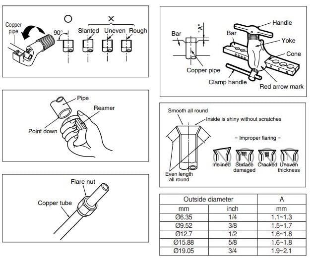
Putting nut on
- Remove flare nuts attached to indoor and outdoor unit, then put them on pipe/tube having completed burr removal. (not possible to put them on after flaring work)
Flaring work
- Firmly hold copper pipe in a Bar in the dimension shown in the table below.
- Carry out flaring work with the flaring tool.
Check
- Compare the flared work with the figure by.
- If a flared section is defective, cut it off and do flaring work again.
Connecting the Piping

Indoor
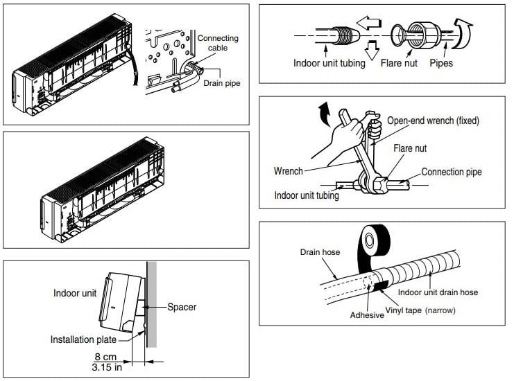
- Prepare the indoor unit’s piping and drain hose for installation through the wall.
- Remove the plastic tubing retainer(see the illustration by) and pull the tubing and drain hose away from chassis.
- Replace only the plastic tubing holder 1, not the holder 2 in the original position.
For right rear piping
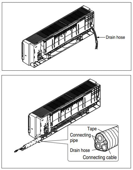
- Route the indoor tubing and the drain hose in the direction of rear right.
- Insert the connecting cable into the indoor unit from the outdoor unit through the piping hole.
- Tape the tubing, drain hose, and the connecting cable. Be sure that the drain hose is located at the lowest side of the bundle. Locating at the upper side can cause drain pan to overflow inside the unit.
- Indoor unit installation Hook the indoor unit onto the upper portion of the installation plate.(Engage the two hooks of the rear top of the indoor unit with the upper edge of the installation plate.) Ensure that the hooks are properly seated on the installation plate by moving it left and right.
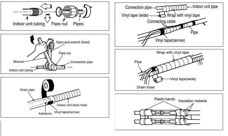
Connecting the piping to the indoor unit and drain hose to drain pipe
- Align the center of the pipes and sufficiently tighten the flare nut by hand.
- Tighten the flare nut with a wrench
- When extending the drain hose at the indoor unit, install the drain pipe.
Wrap the insulation material around the connecting portion
- Overlap the connection pipe insulation material and the indoor unit pipe insulation material. Bind them together with vinyl tape so that there may be no gap.
- Wrap the area which accommodates the rear piping housing section with vinyl tape.
- Bundle the piping and drain hose together by wrapping them with vinyl tape for enough to cover where they fit into the rear piping housing section.
For left rear piping
- Route the indoor tubing and the drain hose to the required piping hole position.
- Insert the piping, drain hose, and the connecting cable into the piping hole.
- Insert the connecting cable into the indoor unit.
- Tape the drain hose and the connecting cables.
- Indoor unit installation
Connecting the piping to the indoor unit and the drain hose to drain pipe.
- Align the center of the pipes and sufficiently tighten the flare nut by hand.
- Tighten the flare nut with a wrench.
- When extending the drain hose at the indoor unit, install the drain pipe.
Wrap the insulation material around the connecting portion.
- Overlap the connection pipe heat insulation and the indoor unit pipe heat insulation material. Bind them together with vinyl tape so that there may be no gap.
- Wrap the area which accommodates the rear piping housing section with vinyl tape.
- Bundle the piping and drain hose together by wrapping them with cloth tape over the range within which they fit into the rear piping housing section
Indoor unit installation
- Remove the spacer.
- Ensure that the hooks are properly seated on the installation plate by moving it left and right.
- Press the lower left and right sides of the unit against the installation plate until the hooks engage into their slots(clicking sound)
Outdoor
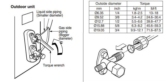
Align the center of the pipings and sufficiently tighten the flare nut by hand.
Finally, tighten the flare nut with torque wrench until the wrench clicks.
- When tightening the flare nut with torque wrench, ensure the direction for tightening follows the arrow on the wrench.
Connecting the Cables
Indoor
Connect the cable to the indoor unit by connecting the wires to the terminals on the control board individually according to the outdoor unit connection. (Ensure that the color of the wires of the outdoor unit and the terminal No. are the same as those of the indoor unit.)
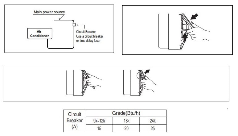
How to use the front panel
1. Front panel closing
Move the link upward and close the front panel.
2. Front panel removing
Raise the link up to hook hanger and remove front panel forward
Outdoor
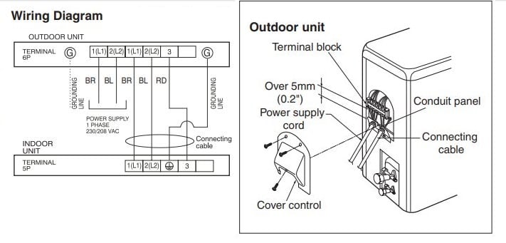
- Remove the cover control from the unit by loosening the screw. Connect the wires to the terminals on the control board individually as the following.
- Secure the cable onto the control board with the holder (clamper).
- Refix the cover control to the original position with the screw.
How to connect wiring to the terminals
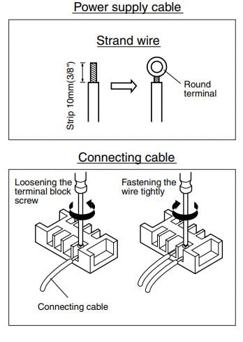
For strand wiring
- Cut the wire end with a wire cutter or wirecutting pliers, then strip the insulation to expose the strand wiring about 10mm(3/8″).
- Using a screwdriver, remove the terminal screw(s) on the terminal plate.
- Using a round terminal fastener or pliers, securely clamp each stripped wire end with a round terminal.
- Position the round terminal wire, and replace and tighten the terminal screw using a screwdriver
Checking the Drainage
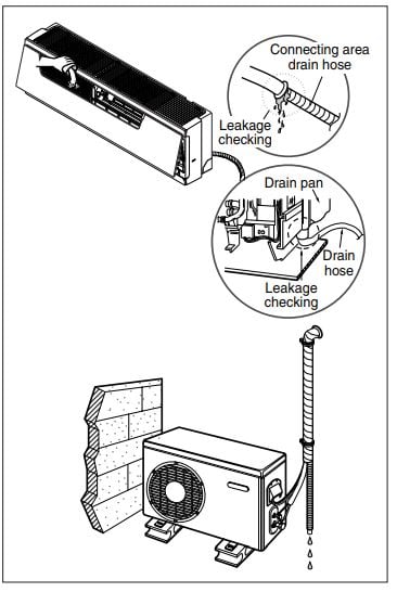
To check the drainage
- Pour a glass of water on the evaporator.
- Ensure the water flows through the drain hose of the indoor unit without any leakage and goes out the drain exit.
Drain piping
- The drain hose should point downward for easy drain flow.
- Do not make drain piping like the following.
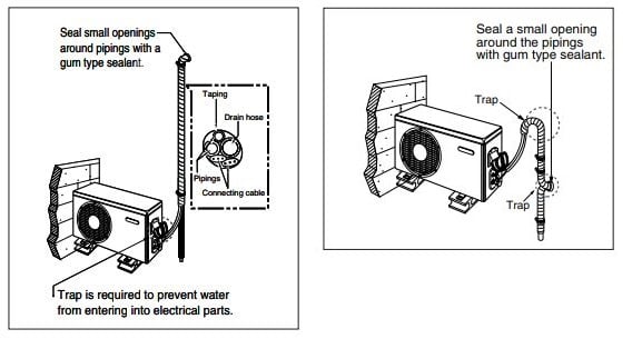
Forming the Piping
Form the piping by wrapping the connecting portion of the indoor unit with insulation material and secure it with two kinds of vinyl tapes.
- If you want to connect an additional drain hose, the end of the drain outlet should be routed above the ground. Secure the drain hose appropriately
- In cases where the outdoor unit is installed below the indoor unit perform the following.
- Tape the piping, drain hose and connecting cable from down to up.
- Secure the tapped piping along the exterior wall using saddle or equivalent.
In cases where the Outdoor unit is installed above the Indoor unit perform the following.
- Tape the piping and connecting cable from down to up.
- Secure the taped piping along the exterior wall. Form a trap to prevent water entering the room.
- Fix the piping onto the wall by saddle or equivalent.
Air Purging
The air and moisture remaining in the refrigerant system have undesirable effects as indicated below.
- Pressure in the system rises.
- Operating current rises.
- Cooling(or heating) efficiency drops.
- Moisture in the refrigerant circuit may freeze and block capillary tubing.
- Water may lead to corrosion of parts in the refrigeration system. Therefore, after evacuating the system, take a leak test for the piping and tubing between the indoor and outdoor unit.
Air purging with vacuum pump
Preparation
- Check that each tube(both liquid and gas side tubes) between the indoor and outdoor units have been properly connected and all wiring for the test run has been completed. Remove the service valve caps from both the gas and the liquid side on the outdoor unit. Note that both the liquid and the gas side service valves on the outdoor unit are kept closed at this stage.
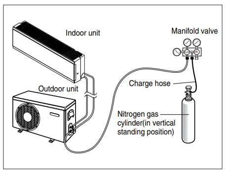
Leak test
- Connect the manifold valve(with pressure gauges) and dry nitrogen gas cylinder to this service port with charge hoses.
Soap water method
- Remove the caps from the 2-way and 3-way valves.
- Remove the service-port cap from the 3-way valve.
- To open the 2-way valve turn the valve stem counterclockwise approximately 90°, wait for about 2~3 sec, and close it.
- Apply a soap water or a liquid neutral detergent on the indoor unit connection or outdoor unit connections by a soft brush to check for leakage of the connecting points of the piping.
- If bubbles come out, the pipes have leakage
Evacuation
- Connect the charge hose end described in the preceding steps to the vacuum pump to evacuate the tubing and indoor unit. Confirm the “Lo” and “Hi” knob of the manifold valve is open. Then, run the vacuum pump. The operation time for evacuation varies with tubing length and capacity of the pump. The following table shows the time required for evacuation
- When the desired vacuum is reached, close the “Lo” and “Hi” knob of the manifold valve and stop the vacuum pump
Finishing the job
- With a service valve wrench, turn the valve stem of liquid side valve counter-clockwise to fully open the valve.
- Turn the valve stem of gas side valve counterclockwise to fully open the valve.
- Loosen the charge hose connected to the gas side service port slightly to release the pressure, then remove the hose.
- Replace the flare nut and its bonnet on the gas side service port and fasten the flare nut securely with an adjustable wrench. This process is very important to prevent leakage from the system.
- Replace the valve caps at both gas and liquid side service valves and fasten them tight. This completes air purging with a vacuum pump. The air conditioner is now ready to test run.
Test Running
- Check that all tubing and wiring are properly connected.
- Check that the gas and liquid side service valves are fully open.
Prepare remote controller
- Remove the battery cover by pulling it according to the arrow direction.
- Insert new batteries making sure that the (+) and (–) of battery are installed correctly.
- Reattach the cover by pushing it back into position.
Settlement of outdoor unit
- Anchor the outdoor unit with a bolt and nut[ø10mm(0.39in)] tightly and horizontally on a concrete or rigid mount.
- When installing on the wall, roof or rooftop, anchor the mounting base securely with a nail or wire assuming the influence of wind and earthquake.
- If the vibration of the unit is transmitted to the hose, secure the unit with an anti-vibration rubber.
Evaluation of the performance
Operate the unit for 15~20 minutes, then check the system refrigerant charge:
- Measure the pressure of the gas side service valve.
- Measure the temperature of the intake and discharge of air.
- Ensure the difference between the intake temperature and the discharge is more than 8°C
- For reference; the gas side pressure of optimum condition is as below.(Cooling)
Installation guide at the seaside
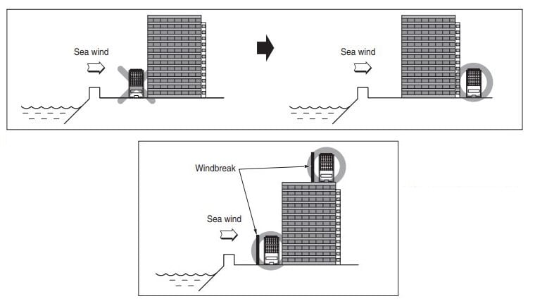
Selecting the location (Outdoor Unit)
- If the outdoor unit is to be installed close to the seaside, direct exposure to the sea wind should be avoided. Install the outdoor unit on the opposite side of the sea wind direction.
- In case, to install the outdoor unit on the seaside, set up a windbreak not to be exposed to the sea wind.
- Select a well-drained place.
Air Conditioner Cleaning and Maintenance-Guide and Checklist
contact: leehall@lobpro.com
- How to change phone ip address? - October 26, 2025
- How Do I Choose a Central Air Conditioner? AC Buying Guide - October 1, 2025
- How to Change Your Home Air Conditioner Filter? - September 14, 2025